BOT19000 QWIIC Base Board Datasheet
Overview
Description
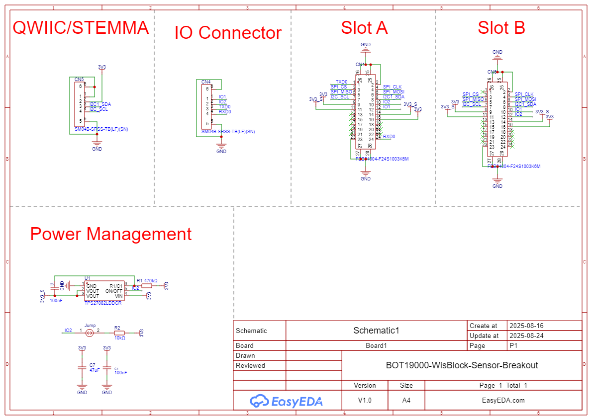
BOT19000 is a base board based on the WisBlock standard that mimics the sensor slots A and B. It has a QWIIC connector for power and I2C, a NON QWIIC connector for RX, TX, and IO 1 and 2, and lastly it has solder pads on the back for SPI.
Features
- Module specifications
- QWIIC Power & I2C Connector - Standard QWIIC JST SH 4-pin connector for power and I2C.
- Dual Sensor Slots - Slot A and Slot B for WisBlock sensor modules
- Compact Form Factor - 18x37mm PCB with 4 mounting holes for secure installation
- Power Management - TPS27082LDDCR load switch for S_3V3 rail control via WB_IO2
- WisBlock Compatible - Full compatibility with WisBlock sensor module ecosystem
- Mounting Options - 4 strategically placed mounting holes for versatile installation
Specifications
Overview

Hardware
Pin Definition WisBlock Sensor Slot Pinout (24-pin Connector
| Connector B | Connector A | Pin Number | Pin Number | Connector A | Connector B |
|---|---|---|---|---|---|
| NC | TXD1 | 1 | 2 | GND | GND |
| SPI_CS | SPI_CS | 3 | 4 | SPI_CLK | SPI_CLK |
| SPI_MISO | SPI_MISO | 5 | 6 | SPI_MOSI | SPI_MOSI |
| I2C1_SCL | I2C1_SCL | 7 | 8 | I2C1_SDA | I2C1_SDA |
| VDD | VDD | 9 | 10 | IO2 | IO1 |
| 3V3_S | 3V3_S | 11 | 12 | IO1 | IO2 |
| NC | NC | 13 | 14 | 3V3 | 3V3 |
| NC | NC | 15 | 16 | NC | NC |
| NC | NC | 17 | 18 | NC | NC |
| NC | NC | 19 | 20 | NC | NC |
| NC | NC | 21 | 22 | NC | NC |
| GND | GND | 23 | 24 | RXD1 | NC |
⚠️ POWER LIMITATION
- System Current Limit: Maximum 226mA total system current (Qwiic cable limit)
- Power Budget: VDD (pin 9) provides 3V3_S switched power, limited by total Qwiic input
- 3V3 (pin 14): Always-on power rail, shares the same 226mA budget
- Multiple Sensors: Total current consumption of all sensors must not exceed 226mA
- The connector is 100% compatible with all existing WisBlock sensor modules within power limits
Electrical Characteristics
This section shows the maximum and minimum ratings of the BOT14000 module and its recommended operating conditions. Refer to the table presented below.
QWIIC Cable

Most QWIIC cables follow the color scheme and arrangement in the table below:
| Wire Color | Label |
|---|---|
| Black | GND |
| Red | 3.3 V |
| Blue | SDA |
| Yellow | SCL |
Warning
The recommended maximum current on a QWIIC cable is 226 mA.
I2C Troubleshooting
If experiencing communication issues or erratic behavior with multiple I2C devices connected, try cutting the JP1 jumper to disable pull-up resistors. This permanent modification resolves bus loading conflicts common with 3+ devices on the same I2C bus.
Power Supply (via QWIIC Cable 3V3_S)
| Parameter | Min | Typ | Max | Unit | Conditions |
|---|---|---|---|---|---|
| Operating Voltage (VDD) | 3.0 | 3.3 | 3.6 | V | Via QWIIC connector (3V3_S) |
| Display Current (Static) | 15 | 20 | 25 | mA | All pixels ON |
| Display Current (Typical) | 5 | 10 | 15 | mA | 50% pixels ON |
| Standby Current | 1 | 2 | 5 | µA | Display OFF mode |
| Power-up Time | 100 | 200 | 300 | ms | After 3V3_S activation |
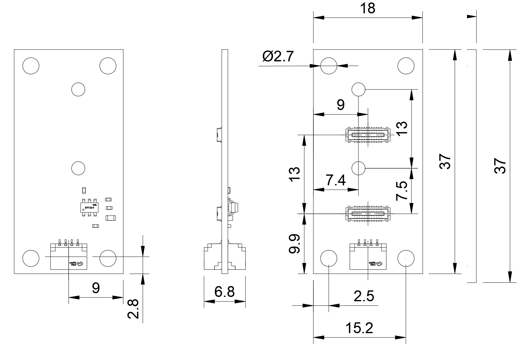
Mechanical Characteristics
Board Dimensions
Schematic Diagram